Case Study: CCNA Cap Stone
- Advanced Routing
- WAN simulation
- Frame Relay
- ISDN
- PPP
- DDR
- CHAP
- VLANS
- NAT
- DHCP
- Trunking
- Access Lists
- Security
Case Study: CCNA Cap Stone
This case study consists of three parts. In the first you will need to design and implement a network for a video game company Activision and connecting their network to the ISP. The second part consists of creating a redundant network for a Californian ISP Succeed.net and connecting it to their upstream carrier. Third your task will be to configure a network for a small oil and natural gas exploration company, Ultra Petroleum and connect their network to the Succeed.net ISP. This case study is designed to test the student's proficiency in dealing with all of the most difficult concepts taught in the CCNA curriculum. Not for the weak hearted.
The case study is divided into separate steps. Completing this case study means submitting answers to all in-text questions, IP addressing tables (see figure 1 for details), verifying connectivity, verifying that the access lists enforce the required security policies, and submitting all running configurations of configured network devices (this includes routers, switches as well as Atlas 550 switches). The preferred order of completing all configuration tasks:
- IP address subnet calculations (fill out table as shown in figure 1)
- Access list design
- Interface configuration, Switch IP addressing, ISDN, Frame Relay
- VLAN and Trunking
- Dynamic and Static Routing, Route summarization
- DHCP, NAT, PPP, DDR, Switch-port security
- Access lists
- Connectivity and Access list testing
| Network device | Interface (slot/port) | IP address/network mask | Valid host IP range | Broadcast address |
| Router P1 | e0/0.1 - VLAN 1 | 176.16.0.1/27 | 176.16.0.1 - 176.16.0.30 | 176.16.0.31 |
| Router P1 | e0/0.2 - VLAN 2 | 176.16.0.33/27 | 176.16.0.33 - 176.16.0.62 | 176.16.0.63 |
| Router P1 | e0/0.3 - VLAN 3 | 176.16.0.129/25 | 176.16.0.129 - 176.16.0.254 | 176.16.0.255 |
| Router P1 | e0/0.4 - VLAN 4 | 176.16.1.1/24 | 176.16.1.1 - 176.16.1.254 | 176.16.1.255 |
| Router P1 | e0/0.5 - VLAN 5 | 176.16.2.1/24 | 176.16.2.1 - 176.16.2.254 | 176.16.2.255 |
| Router P1 | s0/0 - DCE | 176.16.3.1/30 | 176.16.3.1 - 176.16.3.2 | 176.16.3.3 |
| Switch S3 | VLAN 1 | 176.16.0.2/27 | 176.16.0.1 - 176.16.0.30 | 176.16.0.31 |
| Router R1 | s0/1 - DTE | 176.16.3.5/30 | 176.16.3.5 - 176.16.3.6 | 176.16.3.7 |
| Router R1 | s0/0 - DTE, DLCI 101 | 176.16.3.9/30 | 176.16.3.9 - 176.16.3.10 | 176.16.3.11 |
| Router R1 | e0/0 | 176.16.3.13/30 | 176.16.3.13 - 176.16.3.14 | 176.16.3.15 |
| Router U1 | e0/0 | 176.16.3.17/30 | 176.16.3.17 - 176.16.3.18 | 176.16.3.19 |
| Router U1 | s0/1 - DTE | 176.16.3.21/30 | .... | .... |
| .... | .... | .... | .... | .... |
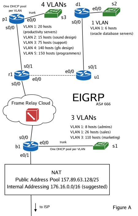
Activision (stock ticker: ATVI), a video game company has just announced that they will create a game based on the story of Shrek 2, and have hired you to design and implement a network for a newly created game development group. You have created and initial network topology (as shown in figure A). After considering the pros and cons you have decided to use EIGRP as you internal routing protocol (please use AS# 666 for the purpose of this case study).
The main development group's hosts have been assigned to VLANs based on their roles. These are:
- Productivity Servers - will be used by programmers and game designers as source code tree repositories and other development purposes. And estimated number of 20 hosts is needed on this VLAN.
- Sound Design - this group will be responsible for designing the music and sound effects for the game. About 15 hosts.
- Programmers - core engine coder group. About 150 hosts.
- Graphic Design - this group will design the art for the game and create the necessary textures as well as work with the programming group in creating special effects. Estimated number: 140 hosts.
- Support - all other hosts. Estimated number: 75 hosts.
You must assign the second usable IP address from the 157.89.63.0/30 network to the e0/1 interface on the b1 router, for connectivity to the ISP. The ISP has assigned a public IPv4 network of 157.89.63.128/25 for your addressing purposes. As it is clear that this pool of addresses is too small to support all the hosts the branch office will need, you must find a way around this limitation. You will therefore need to use PAT on the b1 router (as illustrated in figure A) to solve this problem.
Your branch office will need a cluster of Oracle database servers for storing various sensitive financial information. These servers should be placed one VLAN with 6 hosts. As this VLAN will connect servers containing sensitive information, all other ports on the s2 switch should be permanently disabled. Enabling port security based on MAC addresses on the switch's ports is advised.
The third and last group of VLANs are to be implemented in a second part (the two parts will be connected with a Frame Relay link from routers r1 and b1) of the branch office. These VLANs are:
- Administrators - about 8 hosts are to be assigned to a group of administrator who will be governing the network to ensure that it continues to operate smoothly.
- Sales - this regional sales division will require 26 hosts.
- Marketing - as the gaming industry is very highly dependent on marketing, this VLAN will need at least 110 hosts.
Security is a very important issue to the company, that's why the following security policies must be enforced to protect the network.
- Administrators should be able to access every device, on every network within the autonomous system.
- Everyone should be denied establishing connections to the Administrator's VLAN.
- Connections to the Oracle servers should only be allowed for hosts from the Sales and Administrator's VLAN.
- Productivity Servers, Sound Design, Graphics Design, Programmers should be all able to communicate.
- Support, Sound Design, Graphics Design, Programmers should be all able to communicate. Hosts on the Support VLAN shouldn't have access to the Productivity Server's VLAN.
- Productivity Servers, Sales and Marketing should all be able to communicate.
- Everyone except the Productivity Servers, and Oracle Database Servers VLANs should be able to reach the ISP.
- Choose an address pool for internal addressing (176.16.0.0/16 suggested).
- Create subnetworks for internal addressing based on the number of IP addresses that will be needed on the networks. Fill out the supplied IP addressing table.
- Set passwords (secret, console, telnet lines) and password-encryption on all routers and switches.
- Create 4 VLANs on switch s3, 1 VLAN on s2, and 3 VLANs on s1. Assign at least one port on the switch per VLAN. On ports belonging to the Oracle Database VLAN enable port security based on physical addresses.
- Assign IP addresses to each switch for administrative purposes.
- Implement dynamic routing using EIGRP AS# 666.
- Put a description on each router interface and sub-interface.
- Create e0/0 sub-interfaces on p1, d1, and b1 routers to enable routing between VLANs.
- Create a DHCP pool for each VLAN except the VLAN holding the Oracle database servers. Supply an appropriate default gateway for each pool. Exclude IP addresses from the DHCP pools to assign to the router interfaces as well as the switches for management purposes.
- Design access lists to implement the company's security policy. Determine where to most effectively apply each access list.
- Setup Port Address Translation on the b1 router between the assigned public IP address pool and your internal addressing.
- Disable sending routing updates through e0/1 on b1. Create a default route, and redistribute it throughout the network dynamically.
- Create a Frame Relay PVC between r1 and b1 routers using an Adtran Atlas 550 as a Frame Relay switch.
- Disable Spanning-Tree Protocol on all the switches.
- Solve any possible problems that might arise due to automatic route summarization.
- Verify connectivity, and access lists. Use supplied connectivity testing table.
| Network device | Interface (slot/port) | IP address/network mask | Valid host IP range | Broadcast address |
| Router P1 | ||||
| Router P1 | ||||
| Router P1 | ||||
| Router P1 | ||||
| Router P1 | ||||
| Router R1 | ||||
| Router R1 | ||||
| Router R1 | ||||
| Router U1 | ||||
| Router U1 | ||||
| Router D1 | ||||
| Router D1 | ||||
| Router B1 | ||||
| Router B1 | ||||
| Router B1 | ||||
| Router B1 | ||||
| Router B1 | ||||
| Switch S1 | ||||
| Switch S2 | ||||
| Switch S3 |
| Source | Destination | Action | Expected Result | Result |
| Host on Switch S3 - VLAN 1 | Host on Switch S3 - VLAN 1 | Ping | success | |
| Host on Switch S3 - VLAN 1 | Host on Switch S3 - VLAN 2 | Ping | success | |
| Host on Switch S3 - VLAN 1 | Host on Switch S3 - VLAN 3 | Ping | failure | |
| Host on Switch S3 - VLAN 1 | Host on Switch S3 - VLAN 4 | Ping | success | |
| Host on Switch S3 - VLAN 1 | Host on Switch S3 - VLAN 5 | Ping | success | |
| Host on Switch S3 - VLAN 1 | Host on Switch S2 - VLAN 1 | Ping | failure | |
| Host on Switch S3 - VLAN 1 | Host on Switch S1 - VLAN 1 | Ping | failure | |
| Host on Switch S3 - VLAN 1 | Host on Switch S1 - VLAN 2 | Ping | success | |
| Host on Switch S3 - VLAN 1 | Host on Switch S1 - VLAN 3 | Ping | success | |
| Host on Switch S3 - VLAN 1 | e0/0 on Router B2 | Ping | failure | |
| Host on Switch S3 - VLAN 1 | Upstream Carrier | Ping | failure | |
| Host on Switch S3 - VLAN 2 | Host on Switch S3 - VLAN 2 | Ping | success | |
| Host on Switch S3 - VLAN 2 | Host on Switch S3 - VLAN 3 | Ping | success | |
| Host on Switch S3 - VLAN 2 | Host on Switch S3 - VLAN 4 | Ping | success | |
| Host on Switch S3 - VLAN 2 | Host on Switch S3 - VLAN 5 | Ping | success | |
| Host on Switch S3 - VLAN 2 | Host on Switch S2- VLAN 1 | Ping | failure | |
| Host on Switch S3 - VLAN 2 | Host on Switch S1- VLAN 1 | Ping | failure | |
| Host on Switch S3 - VLAN 2 | Host on Switch S1 - VLAN 2 | Ping | failure | |
| Host on Switch S3 - VLAN 2 | Host on Switch S1 - VLAN 3 | Ping | failure | |
| Host on Switch S3 - VLAN 2 | e0/0 on Router B2 | Ping | success | |
| Host on Switch S3 - VLAN 2 | Upstream Carrier | Ping | success | |
| Host on Switch S3 - VLAN 3 | Host on Switch S3 - VLAN 3 | Ping | success | |
| Host on Switch S3 - VLAN 3 | Host on Switch S3 - VLAN 4 | Ping | success | |
| Host on Switch S3 - VLAN 3 | Host on Switch S3 - VLAN 5 | Ping | success | |
| Host on Switch S3 - VLAN 3 | Host on Switch S2 - VLAN 1 | Ping | failure | |
| Host on Switch S3 - VLAN 3 | Host on Switch S1- VLAN 1 | Ping | failure | |
| Host on Switch S3 - VLAN 3 | Host on Switch S1- VLAN 2 | Ping | failure | |
| Host on Switch S3 - VLAN 3 | Host on Switch S1 - VLAN 3 | Ping | failure | |
| Host on Switch S3 - VLAN 3 | e0/0 on Router B2 | Ping | success | |
| Host on Switch S3 - VLAN 3 | Upstream Carrier | Ping | success | |
| Host on Switch S3 - VLAN 4 | Host on Switch S3 - VLAN 4 | Ping | success | |
| Host on Switch S3 - VLAN 4 | Host on Switch S3 - VLAN 5 | Ping | success | |
| Host on Switch S3 - VLAN 4 | Host on Switch S2 - VLAN 1 | Ping | failure | |
| Host on Switch S3 - VLAN 4 | Host on Switch S1 - VLAN 1 | Ping | failure | |
| Host on Switch S3 - VLAN 4 | Host on Switch S1- VLAN 2 | Ping | failure | |
| Host on Switch S3 - VLAN 4 | Host on Switch S1- VLAN 3 | Ping | failure | |
| Host on Switch S3 - VLAN 4 | e0/0 on Router B2 | Ping | success | |
| Host on Switch S3 - VLAN 4 | Upstream Carrier | Ping | success | |
| Host on Switch S3 - VLAN 5 | Host on Switch S3 - VLAN 5 | Ping | success | |
| Host on Switch S3 - VLAN 5 | Host on Switch S2 - VLAN 1 | Ping | failure | |
| Host on Switch S3 - VLAN 5 | Host on Switch S1 - VLAN 1 | Ping | failure | |
| Host on Switch S3 - VLAN 5 | Host on Switch S1 - VLAN 2 | Ping | failure | |
| Host on Switch S3 - VLAN 5 | Host on Switch S1- VLAN 3 | Ping | failure | |
| Host on Switch S3 - VLAN 5 | e0/0 on Router B2 | Ping | success | |
| Host on Switch S3 - VLAN 5 | Upstream Carrier | Ping | success | |
| Host on Switch S2 - VLAN 1 | Host on Switch S1 - VLAN 1 | Ping | failure | |
| Host on Switch S2 - VLAN 1 | Host on Switch S1 - VLAN 2 | Ping | success | |
| Host on Switch S2 - VLAN 1 | Host on Switch S1 - VLAN 3 | Ping | failure | |
| Host on Switch S2 - VLAN 1 | e0/0 on Router B2 | Ping | failure | |
| Host on Switch S2 - VLAN 1 | Upstream Carrier | Ping | failure | |
| Host on Switch S1 - VLAN 1 | Host on Switch S1 - VLAN 1 | Ping | success | |
| Host on Switch S1 - VLAN 1 | Host on Switch S1 - VLAN 2 | Ping | success | |
| Host on Switch S1 - VLAN 1 | Host on Switch S1 - VLAN 3 | Ping | success | |
| Host on Switch S1 - VLAN 1 | e0/0 on Router B2 | Ping | success | |
| Host on Switch S1 - VLAN 1 | Upstream Carrier | Ping | success | |
| Host on Switch S1 - VLAN 2 | Host on Switch S1 - VLAN 2 | Ping | success | |
| Host on Switch S1 - VLAN 2 | Host on Switch S1 - VLAN 3 | Ping | success | |
| Host on Switch S1 - VLAN 2 | e0/0 on Router B2 | Ping | success | |
| Host on Switch S1 - VLAN 2 | Upstream Carrier | Ping | success | |
| Host on Switch S1 - VLAN 3 | Host on Switch S1 - VLAN 3 | Ping | success | |
| Host on Switch S1 - VLAN 3 | e0/0 on Router B2 | Ping | success | |
| Host on Switch S1 - VLAN 3 | Upstream Carrier | Ping | success | |
| Router D1 | Router U3 | Ping | success | |
| Router D1 | Upstream Carrier | Ping | success | |
| Router P1 | Router P4 | Ping | success | |
| Host on Switch S1 - VLAN 1 | Host on Switch S3 - VLAN 1 | Telnet | success | |
| Host on Switch S1 - VLAN 1 | Host on Switch S3 - VLAN 2 | Telnet | success | |
| Host on Switch S1 - VLAN 1 | Host on Switch S3 - VLAN 3 | Telnet | success | |
| Host on Switch S1 - VLAN 1 | Host on Switch S3 - VLAN 4 | Telnet | success | |
| Host on Switch S1 - VLAN 1 | Host on Switch S3 - VLAN 5 | Telnet | success | |
| Host on Switch S1 - VLAN 1 | Host on Switch S2 - VLAN 1 | Telnet | success | |
| Host on Switch S1 - VLAN 1 | Host on Switch S1 - VLAN 2 | Telnet | success | |
| Host on Switch S1 - VLAN 1 | Host on Switch S1 - VLAN 3 | Telnet | success | |
| Host on Switch S3 - VLAN 1 | Host on Switch S1 - VLAN 1 | Telnet | success | |
| Host on Switch S3 - VLAN 2 | Host on Switch S1 - VLAN 1 | Telnet | failure | |
| Host on Switch S3 - VLAN 3 | Host on Switch S1 - VLAN 1 | Telnet | failure | |
| Host on Switch S3 - VLAN 4 | Host on Switch S1 - VLAN 1 | Telnet | failure | |
| Host on Switch S3 - VLAN 5 | Host on Switch S1 - VLAN 1 | Telnet | failure | |
| Host on Switch S2 - VLAN 1 | Host on Switch S1 - VLAN 1 | Telnet | failure | |
| Host on Switch S1 - VLAN 2 | Host on Switch S1 - VLAN 1 | Telnet | failure | |
| Host on Switch S1 - VLAN 3 | Host on Switch S1 - VLAN 1 | Telnet | failure |
Succeed.net ISP, based in California, this small ISP has suffered from a large scale Denial of Service attack in 1998 resulting in the lack of network connectivity for a majority of its 150,000 customers. Those responsible for the attack have not yet been apprehended. Your task as a new member of the company's administration team is to design a secure and redundant backbone network, as well as a number of company LANs that will need to be connected to the backbone.
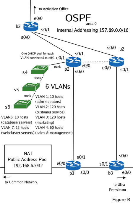
Your company owns the 157.89.0.0/16 network space, which you must subnet to use for your internal addressing and your two clients Activision and Ultra Petroleum. You have already decided to give Activision the 157.89.63.128/25 subnetwork, and a 157.89.64.0/23 subnetwork to Ultra Petroleum.
An initial network topology has been designed (figure B). Your first task is to subnet your internal network using the a subnet of the 157.89.0.0/16 network. The company has the following logical groups of hosts:
- Database Servers - about 10 hosts.
- Web-cluster Servers - include multiple Linux servers with mirrored content and one Linux server running Apache, acting as a transparent proxy that load balances user requests across the servers. About 12 hosts. This network is estimated to grow by as much as 200% in the future.
- Administration - this VLAN will connect all administration host. Currently only 10 host addresses are needed. However, in the future this network is expected to grow by another 10-20 hosts.
- Customer Service - groups all company employees responsible for customer server activities that include: troubleshooting user problems, helping with remote network setup, answering customer and potential customer questions. Requires 120 hosts.
- Marketing - all users responsible for the company's marketing activities are grouped in this network. Requires 120 hosts.
- Sales and Management - this subnetwork contains all hosts belonging to employees from the Sales division and Management. 60 hosts will be needed.
Administration, Customer Service, Marketing, and Sales and Management VLANs will each have a DHCP pool assigned to it and configured on the p2 router.
You have chosen OSPF as your internal routing protocol. Disable sending routing updates beyond your network borders - shown in figure B.
Setup the interfaces e0/0 of router b2 and e0/0 of router b3 with the addresses 157.89.63.1/30 and 157.89.63.5/30 respectively. Use static routes on the b2 and b3 routers to setup traffic forwarding to Activision's and Ultra Petroleum's networks respectively. Redistribute these routes throughout your AS dynamically.
Finally configure connectivity to your upstream carrier. Attach interface e0/0 of the p3 router to your common network and assign it an address on your network. Use PAT to establish connectivity between your internally addressed network (157.89.0.0/16) and your common network. Use a default route to route traffic to e0/0. Redistribute this route through the network dynamically.
Design access lists to enforce the following policies:
- The administrators should be able to reach everything within the AS.
- Anybody should be able to reach the web-cluster server VLAN
- The database servers, marketing, sales & management VLANs should have connectivity.
- The database servers VLAN should be denied connectivity to anywhere else except marketing, sales & management and the administrators.
- Everyone should be denied establishing connections to the Administrator's VLAN.
- Anybody should be able to reach the Customer Service VLAN.
- Everybody except the database servers VLAN should be able to reach the upstream carrier.
- Create subnetworks for internal addressing based on the number of IP addresses that will be needed on the networks. Fill out the supplied IP addressing table.
- Set passwords (secret, console, telnet lines) and password-encryption on all routers and switches.
- Create 4 VLANs on switch s4, s5, and s6. Assign at least one port on each switch to each VLAN. On ports belonging to the Database Servers VLAN enable port security based on physical addresses.
- Setup appropriate trunking ports between the s4, s5, and s6 switches. Use Gigabit Ethernet uplink ports and Cat6 cables (if possible).
- Assign IP addresses to each switch for administrative purposes.
- Implement dynamic routing using OSPF.
- Put a description on each router interface and sub-interface.
- Create e0/0 sub-interfaces on p2 to enable routing between VLANs.
- Create a DHCP pool for each VLAN. Supply an appropriate default gateway for each pool.
- Design access lists to employ the company's security policy. Determine where to most effectively apply each access list.
- Setup Port Address Translation on the p3 router between the assigned public IP address pool and your internal addressing.
- Disable sending routing updates through e0/0 on b2 and e0/0 on b3. Create a default routes to the Activision's and Ultra Petroleum's networks, and redistribute them throughout the network dynamically.
- Disable Spanning-Tree Protocol on all the switches.
- Solve any possible problems that might arise due to automatic route summarization.
- Make sure that OSPF routing updates sent through e0/0 are summarized as 157.89.0.0/16
- Verify connectivity, and access lists. Use supplied connectivity testing table.
| Network device | Interface (slot/port) | IP address/network mask | Valid host IP range | Broadcast address |
| Router B2 | ||||
| Router B2 | ||||
| Router B2 | ||||
| Router P2 | ||||
| Router P2 | ||||
| Router P2 | ||||
| Router P2 | ||||
| Router P2 | ||||
| Router P2 | ||||
| Router P2 | ||||
| Router P2 | ||||
| Router P2 | ||||
| Router U2 | ||||
| Router U2 | ||||
| Router U2 | ||||
| Router P3 | ||||
| Router P3 | ||||
| Router P3 | ||||
| Router B3 | ||||
| Router B3 | ||||
| Router B3 |
| Source | Destination | Action | Expected Result | Result |
| VLAN 1 | VLAN 1 | Ping | success | |
| VLAN 1 | VLAN 2 | Ping | success | |
| VLAN 1 | VLAN 3 | Ping | success | |
| VLAN 1 | VLAN 4 | Ping | success | |
| VLAN 1 | VLAN 5 | Ping | success | |
| VLAN 1 | VLAN 6 | Ping | success | |
| VLAN 1 | e0/0 on Router B4 | Ping | success | |
| VLAN 1 | e0/1 on Router B1 | Ping | success | |
| VLAN 1 | Upstream Carrier | Ping | success | |
| VLAN 2 | VLAN 2 | Ping | success | |
| VLAN 2 | VLAN 3 | Ping | success | |
| VLAN 2 | VLAN 4 | Ping | success | |
| VLAN 2 | VLAN 5 | Ping | failure | |
| VLAN 2 | VLAN 6 | Ping | failure | |
| VLAN 2 | e0/0 on Router B4 | Ping | success | |
| VLAN 2 | e0/1 on Router B1 | Ping | success | |
| VLAN 2 | Upstream Carrier | Ping | success | |
| VLAN 3 | VLAN 3 | Ping | success | |
| VLAN 3 | VLAN 4 | Ping | success | |
| VLAN 3 | VLAN 5 | Ping | success | |
| VLAN 3 | VLAN 6 | Ping | success | |
| VLAN 3 | e0/0 on Router B4 | Ping | success | |
| VLAN 3 | e0/1 on Router B1 | Ping | success | |
| VLAN 3 | Upstream Carrier | Ping | success | |
| VLAN 4 | VLAN 4 | Ping | success | |
| VLAN 4 | VLAN 5 | Ping | success | |
| VLAN 4 | VLAN 6 | Ping | success | |
| VLAN 4 | e0/0 on Router B4 | Ping | success | |
| VLAN 4 | e0/1 on Router B1 | Ping | success | |
| VLAN 4 | Upstream Carrier | Ping | success | |
| VLAN 5 | VLAN 5 | Ping | success | |
| VLAN 5 | VLAN 6 | Ping | failure | |
| VLAN 5 | e0/0 on Router B4 | Ping | failure | |
| VLAN 5 | e0/1 on Router B1 | Ping | failure | |
| VLAN 5 | Upstream Carrier | Ping | failure | |
| VLAN 6 | VLAN 6 | Ping | success | |
| VLAN 6 | e0/0 on Router B4 | Ping | success | |
| VLAN 6 | e0/1 on Router B1 | Ping | success | |
| VLAN 6 | Upstream Carrier | Ping | success | |
| VLAN 1 | VLAN 1 | Telnet | success | |
| VLAN 1 | VLAN 2 | Telnet | success | |
| VLAN 1 | VLAN 3 | Telnet | success | |
| VLAN 1 | VLAN 4 | Telnet | success | |
| VLAN 1 | VLAN 5 | Telnet | success | |
| VLAN 1 | VLAN 6 | Telnet | success | |
| VLAN 2 | VLAN 1 | Telnet | failure | |
| VLAN 3 | VLAN 1 | Telnet | failure | |
| VLAN 4 | VLAN 1 | Telnet | failure | |
| VLAN 5 | VLAN 1 | Telnet | failure | |
| VLAN 6 | VLAN 1 | Telnet | failure |
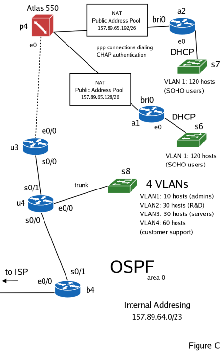
Ultra Petroleum (stock ticker: UPL), a small gas and oil exploration company needs network connectivity between it's two main drilling locations in the Green River Basin, Wyoming and Bohai Bay, China, and its main office in California. It has also hired you to design and implement a corporate network for this fast growing company and provide them with connectivity to the Internet.
You have received a 157.89.64.0/23 IPv4 address pool from the ISP to use for your internal addressing. Your first task will be to subnet this address pool. The company has decided to use PPP connections over ISDN lines for its two drilling locations. You will need to use two ISDN routers with BRIs to accomplish this task.
Each ISDN router (labeled a1 and a2) will also have its own internal, private network of your choice on its e0 interface. The hosts on this network must be configured through DHCP. Assign IP addresses to the s6 and s7 switches. Do not forget to exclude these addresses from the DHCP pools.
Each ISDN router must perform PAT between its bri0 and e0 interfaces. Use the 157.89.65.128/26 and 157.89.65.192/26 pools for the a1 and a2 routers respectively. You will need to create DDR dialers on the ISDN routers to make them connect to the ISDN switch when there is traffic to be sent. Traffic that should be considered interesting by the routers:
- ping
- telnet (TCP, port 23)
- pop3 (TCP, port 110)
- pop3 over SSL (TCP, port 995)
- smtp (TCP, port 25)
- http (TCP, port 80)
- https (TCP, port 443)
- imap (TCP, port 143)
- imap over SSL (TCP, port 993)
Setup the Atlas 550 (or equivalent) ISDN switch to authenticate the PPP connections from the ISDN routers. Use CHAP for authentication purposes. Enable OSPF routing on the ISDN switch. Make sure that p4 and u3 properly exchange routing updates.
Lastly you must setup VLANs on the s8 switch, assign a management IP to it, and create DHCP pools on the p4 router for each of the VLANs attached to it on e0/0. The following VLANs will be needed:
- A 10 host Administration VLAN
- Group of Research & Development hosts. About 30 hosts.
- A Customer Service VLAN that will need 60 hosts.
- A general Servers VLAN with 30 hosts.
The organization has chosen to implement dynamic routing through OSPF. But the following things must be considered:
- Connectivity to the a1 and a2 routers. A static route on the u3 router is suggested.
- Connectivity to the ISP. You must configure the e0/0 interface of the b4 router with the second usable IP address from the 157.89.63.4/30 network, and create a default route to the ISP.
- Finally the ISDN routers must have default routes to the rest of the network.
The company's security policies are pretty straight forward:
- Our administration VLAN should have access everywhere
- Customer Support should only have connectivity to the outside world. The outside world should be able to reach Customer Support.
- Servers, R&D and the ISDN users should have connectivity.
- Everyone expect the hosts on the Servers VLAN should have connectivity to the world.
- Everyone should be denied establishing connections to the Administrator's VLAN.
Design and implement access lists to enforce the above policies.
- Create subnetworks for internal addressing based on the number of IP addresses that will be needed on the networks. Subnet 157.89.64/23 in order to do this. Fill out the supplied IP addressing table.
- Set passwords (secret, console, telnet lines) and password-encryption on all routers and switches.
- Create 4 VLANs on switch s8.
- Assign IP addresses to each switch for administrative purposes.
- Implement dynamic routing using OSPF.
- Put a description on each router interface and sub-interface.
- Create e0/0 sub-interfaces on p4 to enable routing between VLANs.
- Create a DHCP pool for each VLAN. Supply an appropriate default gateway for each pool.
- Create DHCP pools on the ISDN routers. Use address pools that will support at least 120 hosts.
- Setup PAT on the ISDN routers. Using the 157.89.65.128/26 and 157.89.65.192/26 address pools for routers a1 and a2 respectively.
- Design access lists to employ the company's security policy. Determine where to most effectively apply each access list.
- Disable sending routing updates through e0/0 on b4. Create a default route to the ISP. Redistribute this route dynamically.
- Disable Spanning-Tree Protocol on all the switches.
- Solve any possible problems that might arise due to automatic route summarization.
- Create dialers on the ISDN routers to make them automatically establish a PPP connection to the ISDN switch.
- Setup CHAP authentication.
- Setup the ISDN switch to learn routes from u3.
- Make sure connectivity exists between u3 and hosts on s7 and s8 after a PPP connection is established.
- Verify connectivity, and access lists. Use supplied connectivity testing table.
| Network device | Interface (slot/port) | IP address/network mask | Valid host IP range | Broadcast address |
| Router B4 | ||||
| Router B4 | ||||
| Router U4 | ||||
| Router U4 | ||||
| Router U4 | ||||
| Router U4 | ||||
| Router U4 | ||||
| Router U4 | ||||
| Router U3 | ||||
| Router U3 | ||||
| Router P4 | ||||
| Router P4 | ||||
| Router P4 | ||||
| Router A1 | ||||
| Router A1 | ||||
| Router A2 | ||||
| Router A2 |
| Source | Destination | Action | Expected Result | Result |
| Host on Switch S8 - VLAN 1 | Host on Switch S8 - VLAN 1 | Ping | success | |
| Host on Switch S8 - VLAN 1 | Host on Switch S8 - VLAN 2 | Ping | success | |
| Host on Switch S8 - VLAN 1 | Host on Switch S8 - VLAN 3 | Ping | success | |
| Host on Switch S8 - VLAN 1 | Host on Switch S8 - VLAN 4 | Ping | success | |
| Host on Switch S8 - VLAN 1 | e0/0 on Router B3 | Ping | success | |
| Host on Switch S8 - VLAN 1 | Upstream Carrier | Ping | success | |
| Host on Switch S8 - VLAN 2 | Host on Switch S8 - VLAN 2 | Ping | success | |
| Host on Switch S8 - VLAN 2 | Host on Switch S8 - VLAN 3 | Ping | success | |
| Host on Switch S8 - VLAN 2 | Host on Switch S8 - VLAN 4 | Ping | failure | |
| Host on Switch S8 - VLAN 2 | e0/0 on Router B3 | Ping | success | |
| Host on Switch S8 - VLAN 2 | Upstream Carrier | Ping | success | |
| Host on Switch S8 - VLAN 3 | Host on Switch S8 - VLAN 3 | Ping | success | |
| Host on Switch S8 - VLAN 3 | Host on Switch S8 - VLAN 4 | Ping | failure | |
| Host on Switch S8 - VLAN 3 | e0/0 on Router B3 | Ping | success | |
| Host on Switch S8 - VLAN 3 | Upstream Carrier | Ping | success | |
| Host on Switch S8 - VLAN 4 | Host on Switch S8 - VLAN 4 | Ping | success | |
| Host on Switch S8 - VLAN 4 | e0/0 on Router B3 | Ping | success | |
| Host on Switch S8 - VLAN 4 | Upstream Carrier | Ping | success | |
| Router A1 | Host on Switch S8 - VLAN 1 | Ping | failure | |
| Router A1 | Host on Switch S8 - VLAN 2 | Ping | success | |
| Router A1 | Host on Switch S8 - VLAN 3 | Ping | success | |
| Router A1 | Host on Switch S8 - VLAN 4 | Ping | failure | |
| Router A1 | e0/0 on Router B3 | Ping | success | |
| Router A1 | Upstream Carrier | Ping | success | |
| Host on Switch S8 - VLAN 1 | Host on Switch S8 - VLAN 1 | Telnet | success | |
| Host on Switch S8 - VLAN 1 | Host on Switch S8 - VLAN 2 | Telnet | success | |
| Host on Switch S8 - VLAN 1 | Host on Switch S8 - VLAN 3 | Telnet | success | |
| Host on Switch S8 - VLAN 1 | Host on Switch S8 - VLAN 4 | Telnet | success | |
| Host on Switch S8 - VLAN 2 | Host on Switch S8 - VLAN 1 | Telnet | failure | |
| Host on Switch S8 - VLAN 3 | Host on Switch S8 - VLAN 1 | Telnet | failure | |
| Host on Switch S8 - VLAN 4 | Host on Switch S8 - VLAN 1 | Telnet | failure |
|
"He who blames others has a long way to go on his journey. He who blames himself is halfway there. He who blames no one has arrived."
Last update: Thursday, 19th September, 2024 Copyright © 2001-2026 by Lukasz Tomicki |